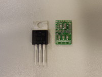
A small PCB the size of a TO-220 case containing a PWM voltage regulator to replace the classic 7805 by a more efficient regulator and with better ripple suppression.
A small PCB the size of a TO-220 case containing a PWM voltage regulator to replace the classic 7805 by a more efficient regulator and with better ripple suppression.
I took over the project and made a PCB which uses a TPS62150 buck convertor to convert a positive potential between 5.5V and 17V to an output of 5V at 1A. If other resistor values are chosen in the feedback loop one can make a version that outputs a different potential. Like 3.3V, 2.5V, 1.8V, 1.5V or 1.2V. I haven't checked the lower voltage input limit of those lower voltages. But I guess it's about 0.5V above the output voltage at 1A output current.
The design still contains R3, for LC filter stability, which might be removed for the final version, if proven to be unnecessary.
Update 1
I managed to assemble it by hand with a hot air solder gun and solder paste. I only had to resolder the IC once, too much paste. And it functions! I just need to do some extensive tests to measure the exact performance.
Update 2
I added some test results in a zip file, I tested it with resistive loads, 4.7Ω, 20Ω and 470Ω. (Uncooled!) And I varied the input voltages to see what the effect is on the efficiency, as that is the major issue with linear regulators.
Update 3
I updated the Excel sheet with some measurents I did in the lab on an 7805. (Cooled!) I put the efficiencies together in the graphs so the difference in efficiency is obvious to see. It is also interresting to take a look at the ouput voltages, the 7805 has a way higher dropout voltage.
Update 4
I did a pulsed load test to see what would happen in an unideal load condition. I attached a 47Ω load and in parrallel a 6.8Ω load switched by an IRF530 N-MOSFET at 50kHz. That is a load step from about 10% to 85%. I am very pleased with the scope images I added here. No instability whatsoever but there is a spike when the load drops from 85% to 10%, but look at the scale, that is a frequency in the MHz range. A ferrite bead in series with the output could easily fix this. But then again, this is no realistic load scenario. I did have 1uF electrolitic caps on the input and output. A small value ceramic cap could be benificial as well.
See also [nodepicker==node/2245==Switched%207905%20Replacement%20(120212)==Switched%207905%20Replacement].
Want to build a project?
Bring your design to life with the Elektor PCB Service, powered by Eurocircuits. Upload the project files and order professionally manufactured PCBs or assembled boards through a proven European production platform.
Supporting KiCad, Eagle, Gerber, and ODB++ formats, the service is suitable for everything from prototypes and validation builds to series production and volume manufacturing.
Veuillez saisir votre adresse électronique. Les instructions de réinitialisation de votre mot de passe vous seront immédiatement envoyées par courriel.
Elektor Magazine est depuis 65 ans l’une des principales sources d’information en électronique pour les ingénieurs, les concepteurs, les start-ups et les entreprises. Notre magazine est soutenu par une communauté active d’ingénieurs en électronique – des étudiants aux professionnels – passionnés par la conception et le partage d’idées innovantes.
Pour eux, nous publions chaque année des centaines de contenus sous différents formats, tels que des articles, des vidéos, des webinaires et d’autres formats d’apprentissage. Notre mission est de partager les connaissances de toutes les manières possibles et d’inspirer les lecteurs avec les dernières évolutions du secteur de l’ingénierie électrique.
Thank you for your vote!
Ajoutez vos commentaires
Thank you for your vote!
Veuillez vous connecter pour ajouter une note ou fermez pour revenir en arrière

Discussion (5 commentaire(s))