
180348 DIY soldering station
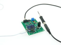
Small soldering station for Weller RT tips. Arduino Leonardo compatible for easy firmware upgrades and extensions over USB. The UI consists of a small OLED display and a rotary encoder.
This is a compact soldering station for the Weller RT tips. Based on the idea of the Platino Soldering Station, this one uses an ATmega32u4 also found in the Arduino Leonardo. This means we can use the Arduino IDE directly to program the MCU and also do firmware uploads thanks to the included bootloader.
The station also has an OLED display and can be controlled by only one knob. But what has changed and what is new?
Since firmware version 1.2 the serial console is included, that allows you to set and read the setpoint of the station, also you can read the current temperature and if any, the errors the station has. You simply can connect the station with a usb cable to the pc and use the arduino ide integrated terminal for the commands. Make sure that you use Newline or Carrigereturn as automatic lineend here. The supported commands can get get from the readme or by typing "help" in the terminal.
Besides that it is based on the Platino version some modifications have been applied. The most important step was to add broken thermocoupler detection to the input stage. If the tip has a bad contact, the station will no longer power the heater to prevent damaging the tip. Also the amplification of the imput voltage has been improved to get a better range, meaning we can better detect if we have a tip with overtemperature. Also you can now messure the current that is flowing through the tip.
For the user input only one rotary encoder (with integrated pushbuton) is needed to operate the iron, and the station has now a 0,96" OLED display instead of the 2x16 alphanumerical LCD used in the Platino version. All these small modifications also mean that we have got new software for the station. But lets take a look to what has changed in the circut.
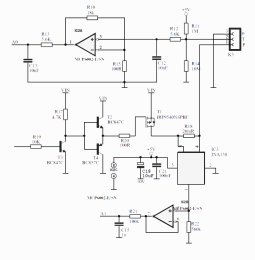 As we can see from the image, the power stage is simple. We have a FET T1, IRF9540, and a driver in front of it. The driver for the FET consists of T3, T2 and T4. T2 and T4 from a push-pull driver and T3 is a level shifter to shift the AVR PWM signal from 5 V to VIN. A 20 mΩ resistor, R18, and an INA138 opamp, are used to measure the current supplied to the tip. But we also need MCP6002 as buffer to avoid the ADC input interfering with the high-impedance output of the INA138. The low-pass filter at the output of the buffer will average the measured current value.
The input for the temperature has a 1MΩ pull-up resitor to 5 V and a 10MΩ pull-down resistor to 0 V at the input. If for some reason the tip is not connected we will get a temperature reading beyond 600°C and can safely assume this to be due to malfuctioning.
The Weller RT tip has a thermo-element inside. Because it produces only a small temperature-dependent voltage amplification is required to use the full resultion of the MCU's ADC.
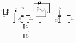 For the power input (24 V max) a small LDO is used for the MCU and the OLED. A diode to protect the board against reversed polarity is present.
A voltage divider R7-R9 allows the MCU to read the actual input voltage. The current firmware has a undervoltage or battery-low detection. If the voltage at the input goes below 10.8 V the tip is no longer powerd. As this is a pretty compact soldering station it can be used in the field powered by one of those cheap Lipo car starter packs.
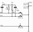 Also of interest may be the rotary encoder. 100 nF capacitors were added to debounce the signals. This may come in handy when the encoder signals are processed in a completly interrupt-driven way. Also note the external pullup resistors that provide a well-defined value. The MCU has its own internally but their values specified to lie somewhere in the range of 20 kΩ to 60 kΩ, in our circuit they have a stable 10 kΩ value.
The OLED is connected to the SPI of the MCU, so nothing special here. Also the USB connection is done according tho the datasheet and doesn't contain any special tricks.
After powering the station a boot logo welcomes you, then the main screen appears. You can see the current temperature, the power supplied to the tip as bargraph and the target temperature set by the user. The station will heat up the tip as soon as the main screen appears. The target temperature is stored in the MCU's EEPROM.
If the station remains idle for ten minutes, it will enter a power down mode and reduce the temperatur to 100°C. If it then remains idle for another 10-minute period, the station will enter sleep mode and display a snoozing tip moving arround the screen. Press the rotary encoder's button to wake the station up again.
1: tip is not heating;
3: temperature sensor connection is bad.
If these errors appear you can confirm them by pressing the rotary encoder's button. Then, if everything is well again, the station resumes working after ten seconds.
The last point to mention is the current limiter. The board will draw an average of 1.5 A by using a maximum duty-cycle of 50% for the PWM control signal. If you have a supply that can handle more than a 1.5 A load, you can adjust the value in the code. The parameter can be found at HW_150500.h for the station.
The station also has an OLED display and can be controlled by only one knob. But what has changed and what is new?
Since firmware version 1.2 the serial console is included, that allows you to set and read the setpoint of the station, also you can read the current temperature and if any, the errors the station has. You simply can connect the station with a usb cable to the pc and use the arduino ide integrated terminal for the commands. Make sure that you use Newline or Carrigereturn as automatic lineend here. The supported commands can get get from the readme or by typing "help" in the terminal.
Besides that it is based on the Platino version some modifications have been applied. The most important step was to add broken thermocoupler detection to the input stage. If the tip has a bad contact, the station will no longer power the heater to prevent damaging the tip. Also the amplification of the imput voltage has been improved to get a better range, meaning we can better detect if we have a tip with overtemperature. Also you can now messure the current that is flowing through the tip.
For the user input only one rotary encoder (with integrated pushbuton) is needed to operate the iron, and the station has now a 0,96" OLED display instead of the 2x16 alphanumerical LCD used in the Platino version. All these small modifications also mean that we have got new software for the station. But lets take a look to what has changed in the circut.
The Hardware
As we can see from the image, the power stage is simple. We have a FET T1, IRF9540, and a driver in front of it. The driver for the FET consists of T3, T2 and T4. T2 and T4 from a push-pull driver and T3 is a level shifter to shift the AVR PWM signal from 5 V to VIN. A 20 mΩ resistor, R18, and an INA138 opamp, are used to measure the current supplied to the tip. But we also need MCP6002 as buffer to avoid the ADC input interfering with the high-impedance output of the INA138. The low-pass filter at the output of the buffer will average the measured current value.The input for the temperature has a 1MΩ pull-up resitor to 5 V and a 10MΩ pull-down resistor to 0 V at the input. If for some reason the tip is not connected we will get a temperature reading beyond 600°C and can safely assume this to be due to malfuctioning.
The Weller RT tip has a thermo-element inside. Because it produces only a small temperature-dependent voltage amplification is required to use the full resultion of the MCU's ADC.
For the power input (24 V max) a small LDO is used for the MCU and the OLED. A diode to protect the board against reversed polarity is present.A voltage divider R7-R9 allows the MCU to read the actual input voltage. The current firmware has a undervoltage or battery-low detection. If the voltage at the input goes below 10.8 V the tip is no longer powerd. As this is a pretty compact soldering station it can be used in the field powered by one of those cheap Lipo car starter packs.
Also of interest may be the rotary encoder. 100 nF capacitors were added to debounce the signals. This may come in handy when the encoder signals are processed in a completly interrupt-driven way. Also note the external pullup resistors that provide a well-defined value. The MCU has its own internally but their values specified to lie somewhere in the range of 20 kΩ to 60 kΩ, in our circuit they have a stable 10 kΩ value.The OLED is connected to the SPI of the MCU, so nothing special here. Also the USB connection is done according tho the datasheet and doesn't contain any special tricks.
The Software
Software is often one of those things that magically appears from out of nowhere and is supposed to work. The software for the previous Platino soldering station was written without the Arduino framework even though it uses an ATmega328P as MCU. This requiered some rework to be done, in this case a new core for the software. As the new and the Platino soldering station have many things in common, the new software was built in a modular way. This means we now need only to maintain one firmware for both stations. The firmware is available at GitHub.After powering the station a boot logo welcomes you, then the main screen appears. You can see the current temperature, the power supplied to the tip as bargraph and the target temperature set by the user. The station will heat up the tip as soon as the main screen appears. The target temperature is stored in the MCU's EEPROM.
If the station remains idle for ten minutes, it will enter a power down mode and reduce the temperatur to 100°C. If it then remains idle for another 10-minute period, the station will enter sleep mode and display a snoozing tip moving arround the screen. Press the rotary encoder's button to wake the station up again.
Errors
If something goes wrong an error screen will pop up displaying the reason of the problem. If for instance undervoltage is detected the current input voltage will be shown. There are also error codes:1: tip is not heating;
3: temperature sensor connection is bad.
If these errors appear you can confirm them by pressing the rotary encoder's button. Then, if everything is well again, the station resumes working after ten seconds.
The last point to mention is the current limiter. The board will draw an average of 1.5 A by using a maximum duty-cycle of 50% for the PWM control signal. If you have a supply that can handle more than a 1.5 A load, you can adjust the value in the code. The parameter can be found at HW_150500.h for the station.
Discussion (6 commentaire(s))