
Android ECG Meter [120107]
A DIY electrocardioscope using an Android tablet or smartphone as a wireless terminal for viewing the electrocardiograms.
It will be a mobile battery powered design (2xAA). With switched power supplies +3,3V and -3,3V is generated.
Some of the things changed by elektor, a different bluetooth module, the first one was twice the price.
Battery polarity reversal protection. Ferrite beads were added to the circuit to isolate noise and to enable the seperation of subcircuits during debugging.
Battery polarity reversal protection. Ferrite beads were added to the circuit to isolate noise and to enable the seperation of subcircuits during debugging.
We chose an all SMD design, single sided components placement, using mostly 0603 passive components. This simplifies the production proces.
Test points will be added for testability purposes.
There are three potmeters in the circuit, they are set only once. If need be they could be replaced by digital potmeters.
Test points will be added for testability purposes.
There are three potmeters in the circuit, they are set only once. If need be they could be replaced by digital potmeters.
Update 18-sep-2012:
The enclosure that was chosen is the PacTec PPL-2AA.
The microcontroller type was changed from PIC24FJ16GA002 to PIC24FJ32GA002 for increased RAM.
An extra resistor of 390K was added between R22 and -3V3 to make sure that the at that point averages to 0V.
An extra resistor of 390K was added between R22 and -3V3 to make sure that the at that point averages to 0V.
R38 is 330K at the moment, but can be changed in the prototype phase.
Update 08-oct-2012:
After reading a comment by the author I changed R14 in the schematic. Instead of being connected behind the MOSFET, it is connected directly to the battery.
Update 25-oct-2012:
I changed connector K1 to this type, on the author's request.
PCB routing is nearly done.
Update 7-dec-2012:
LED types tested with different currentlimit resistor values.
I chose the HSMC-A461-V00M1 which is a red LED in a P-LLC-4 package with a dome on top so it can stick out of the enclosure.
I reached the correct light intensity for pleasant viewing at 3k3 ohms.
(3,3 - 1,7)/3300 = 485uA
A low current use is always good for a battery powered device.
Update 13-dec-2012:
The v1.0 PCB has been finalised and a prototype has been ordered.
The board should arrive next year.
Update 11-jan-2013:
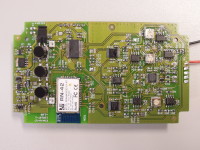
I added a photo of the constructed prototype. Some issues, S2 has to be pressed constantly because there is no firmware in the controller yet.
The boost convertor doesnt seem to be functioning correctly yet.
After trying somethings it seems that the powersupplies are functioning correctly, it's just that there appears to be an unexpectantly large load in the circuit somewhere that loads the positive and negative rails.
Perhaps some opamps mounted the wrong way around...
Update 14-jan-2013:
Indeed, three opamps were mounted the wrong way around. The power use is normal now.
Update 16-jan-2013:
A jumper has been placed over S2 for development ease. The microcontroller has been accessed with a PICKIT2 programmer. It seems to be functional. Also a small mechanical edit was also necessary to fit the PCB properly in the enclosure.
Update 18-jan-2013:
I uploaded the v1.1 PDFs. I also added a component list.
I have sent an email to the author requesting some firmware to test the board.
Also a decision on the type of leads and electrodes has to be reached.
Crucial factors are: price, availibility, quality, hygene.
Update 22-jan-2013:
The author sent a .hex and .apk file. The Android app crashes when doing something with the bluetooth connection. Tested with a Samsung galaxy Tab (android 4.0.4) and an HTC one S (android 4.1.1).
I will have to consult the author.
I will have to consult the author.
I also finished the second prototype.
Update 04-feb-2013:
The software and firmware seem to be functional. It was a bug which the author solved. After calibrating we found that commonmode rejection was not optimal, perhaps a pcb layout issue.
In the second prototype oscillations occur at regular intervals, I'm going to send it to the author and construct a third prototype.
We did a real test on myself, which went just fine. See screenshot.
Update 05-feb-2013:
The 'oscillations' turned out to be a test signal generated by the microcontroller.
Update 14-feb-2013:
IC12 was changed to MCP1640BT, it's the version that does not use the pulseskipping mode. Pulsskipping can cause lowfrequency noise.
IC18,19 and 20 have been reduced in value, from 47k to 10k.
My original prototype shows the calibration signal now as well. One microcontroller pin was not properly soldered.
Update 22-mar-2013:
I added the firmware of the microcontroller and the android app.
The calibration signal is switchable in this version.
Building leads:
To connect the electrodes on your body (limb clamps or stickers) there are a few things to keep in mind.
You are trying to pick up very faint signals, you'd probably use some sort of conductive gel to get a better signal. Anyway, the wires from your elektrodes to your ECG meter is one big antenna. So use shielded cables. Also, most clamps and stickers use either a standard 4mm banana plug or snap-on connectors.
I used RSno. 641-8053 which are banana plugs where you can screw in, instead of soldering it.
And some shielded phono cable from 'van damme', farnellno. 1891102
Then I made a small adapter to connect the cables to connector K1 on the PCB.
Getting electrodes:
I found some affordable ones at praxisdienst.com
Banana to snapon adapters here.
Limb clamps here.
You can get those in four different colours, so you can use the standard ECG colourscheme. i.e.
red => RA (right arm)
yellow => LA (left arm)
green => LL (left leg)
black => RL (right leg)
Want to build a project?
Bring your design to life with the Elektor PCB Service, powered by Eurocircuits. Upload the project files and order professionally manufactured PCBs or assembled boards through a proven European production platform.
Supporting KiCad, Eagle, Gerber, and ODB++ formats, the service is suitable for everything from prototypes and validation builds to series production and volume manufacturing.
Made in Europe. Fast. Reliable. Professional.
Discussion (1 commentaire(s))