
Elektor MultiCalculator Kit
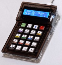
More than just a calculator. Measure light, temperature, differential temperature, decode NEC IR remote control codes and perform other tasks. 22 Modes of operation.
Board and software developed by Ruud van der Meer (RM electronics)
Schematic

Fig.1. Schematic of the MultiCalculator
The MultiCalculator is built around a Pro Mini and is programmable, even after the construction is finished, through a 6way female header at the back. The software is bilingual, the menu language can be Dutch or English. Power supply voltage is 5 V, supplied via a USB-C plug at the back. Current is around 30mA. The design can also be used for other functions (using custom software) and can be programmed via the Arduino IDE. The serial ports have been kept free for monitoring or other functions. There are extra connections on the PCB, e.g.: GND, Reset, D2, D3, A4, A7 (connector H2, not used/fitted in the MultiCalculator). An I2C connection is available (connector P1, also not used/fitted in the MultiCalculator). To use I2C however, the required soldering bridges must be soldered then. Disabling via software is not possible with I2C enabled: dual-solder bridge 2 (I2C/Sw) next to R6 for SDA (A4) and dual-solder bridge 3 (I2C/LDR) next to R9 for SCL (A5). Only one solder bridge must be soldered of each dual-solder bridge on the PCB! The Pro Mini module only has so many I/O ports available. I/O ports A5 and A6 are available on the 3.5mm jack J2, connected by a track in solder bridges SJ1 and SJ2 to pullup resistors of 10kΩ (R11 and R14 respectively). These I/O ports can be used for temperature measurements or other applications (depending on the software). To sever the connections to these pull-up resistors cut the small track between the pads of SJ1 and SJ2. If the connection needs to be restored make a solder bridge between the adjacent pads. The LDR and NTC sensors are always connected to ground, and A5 (LDR/NTC) and A6 (NTC) respectively. On the PCB an NTC can be placed in two locations, R16 or R17. The two connections of R16 and R17 are connected in parallel so only 1 NTC must be mounted! Use R16 and leave R17 unmounted. R16 is farthest away from de module (should it get warm).
An analog input port is used to read switches SW2, SW3, SW4 by changing resistance through the selection of taps of series connection R2 (via D1), R3 and R4. SW2, SW3 are only used to a limited extent in the software. SW5 to SW20 are connected in a matrix. SW1 is used to change the mode of the MultiCalculator and is connected to a separate I/O port (D2). By pressing the MODE switch, the next mode of operation can be chosen. By pressing the mode button longer, the previous mode is chosen. In version 1.1 of the software 22 modes of operation are available.
SW4 is used to turn the MultiCalculator ON or OFF by software, depending on dual-solder bridge 1 next to R3 (On/Sw). If the solder bridge ON is made the MultiCalculator is always powered as soon as 5 V is supplied through the USB-C connector. If solder bridge Sw is made pressing SW4 will turn PNP transistor Q1 ON. It will pull R1 to ground via D2, the power supply is connected to the circuit and the module starts. SW4 must be pushed long enough for the module to make I/O port A4 high. Q1 is turned on through R5 and NPN transistor Q2. If A4 is low the MultiCalculator is switched OFF. The calculator can also be supplied with a voltage of 6-12 volt through the RAW connection on the PCB (J1). A small 5 V voltage regulator is part of the power supply circuit of the Pro Mini module. Switching ON is done by pressing the ON/AC button SW4 for a few seconds until text appears on the display. Switching OFF is done by pressing the ON button for more than 4 seconds. When the key is released, the MultiCalculator is turned off.
Originally the author used a SS8550 for PNP transistor Q1 and a 2SC9013 for NPN transistor Q2 as is indicated on the PCB. Due to availability these were replaced by types KSA708YBU and 2N3904. The exact type is not that critical but if a replacement is necessary pay attention to the pin order of the transistors. The types mentioned here have a different pin order than for instance types BC547 or BC337!
Programming the Arduino Pro Mini can be done via a USB-C to TTL converter (part of the kit). Make sure the jumper on the programming adapter is placed in the 5V position.
The custom enclosure is made of a total of 11 separate transparent acrylic panels. The top panels are dark brown transparent acrylic panels, the rest are clear. A USB-C connector is used connect a 5 V power supply.
Differential temperature measurement.
One mode of operation is not fully clarified in the user manual. To use the differential temperature measurement mode the cable of both waterproof sensors in the kit must be soldered to 3.5 mm plug (also in the kit). The plug can then be inserted in the 3.5 mm jack in the back of the MultiCalculator.
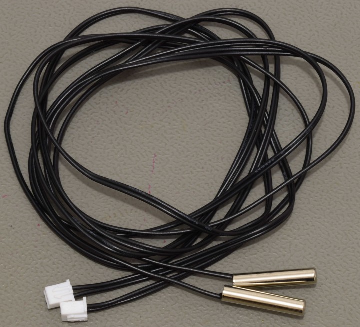
Fig. 2. The waterproof sensors as supplied in the kit
Cut off the connectors from the cables of the waterproof sensors. Each sensor should be soldered to the GND terminal of the 3.5 mm plug and the other wire of each sensor to one of the other contacts of the plug. Best is to cut the ground wires a few mm shorter so the other two are a bit longer and can each be soldered to one of the other 2 contacts of the 3.5 mm plug without having to bend the wires. The plug in the kit can be different than the one shown in the photo. Before soldering don’t forget to place the shell of the 3.5 mm plug over the cables of the sensors first. The plug in the kit can be different from the one shown in the photo.
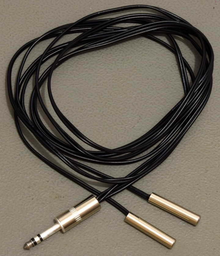
Fig. 3. 2 Waterproof sensors connected to the 3.5 mm plug
Measurements using the waterproof sensors are a bit slow because the NTC is place in a epoxy filled 5 x 25 mm round metal tube. Operating temperature of these sensors is -40 to +85 °C.
Details on construction and a description of all modes of operation can be found in the ‘Construction and User Manual’ (can be downloaded at www.elektor.com). Following photo’s give an impression
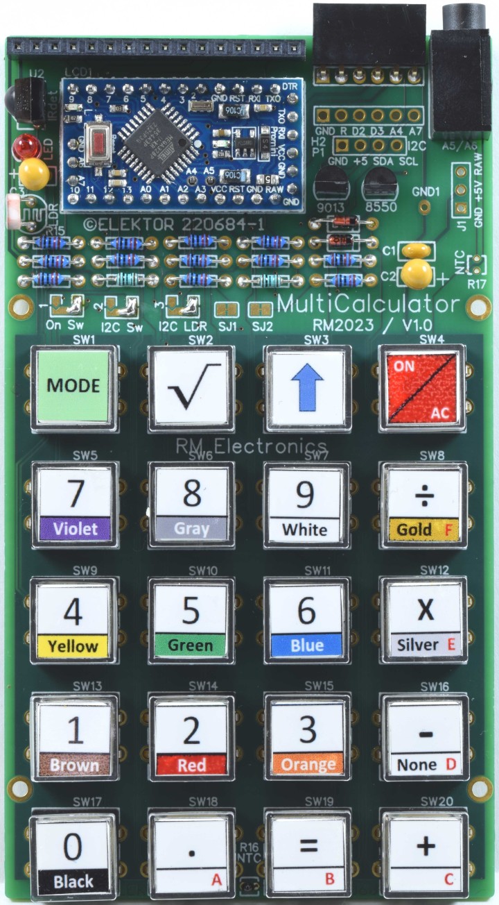
Fig. 4. All parts except the LCD fitted.
A 18.5 mm long pin header must be soldered to the display under an angle. Nothing is bent!
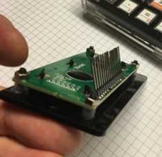
Fig. 5. The header soldered to the display
The USB-C connector must be mounted in the back panel before its wires can be soldered to the PCB.
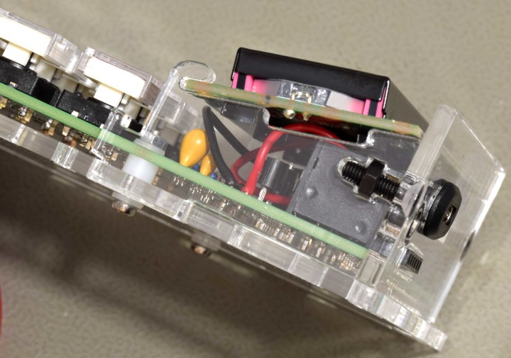
Fig. 6. Detail of back panel, display support with screws and M2 screw of the PCB.
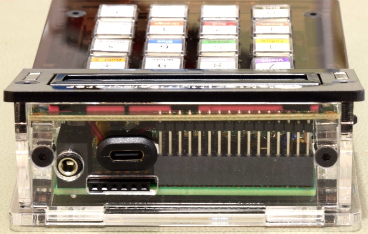
Fig.7. Back of the finished MultiCalculator.
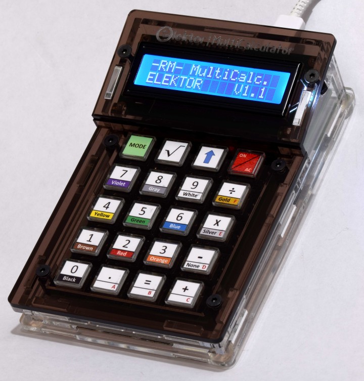
Fig. 8 The MultiCalculator is ready.
Specifications/properties
Power supply voltage 5V (USB-C)
Power supply current ≈ 28…32 mA
ProMini microcontroller module (ATmega328/5V/16MHz)
Programmable by the Arduino IDE (6way female pin header)
2x16 alpha-numerical LCD (LCD 1602, display color blue, white text)
20 labeled pushbuttons
3.5 mm jack to connect external sensors
Operating temperature of waterproof sensors -40 to +85 °C.
22 Menus (software version 1.1)
Functions:
Modes of operation (software v1.1)
1 – Calculator
2 – 4 Ring Resistor Code
3 – 5 Ring Resistor Code
4 – Decimal to Hexadecimal and Character (ASCII) conversion
5 – Hexadecimal to Decimal and Character (ASCII) conversion
6 – Decimal to Binary and Character (ASCII) conversion
7 – Binary to Decimal and Hexadecimal conversion
8 – Hz, nF, reactance Xc calculation
9 – Hz, µH, reactance Xl calculation
10 – Resistance calculation of two resistors connected in parallel
11 – Resistance calculation of two resistors connected in series
12 – Calculation unknown parallel resistor
13 – Temperature measurement
14 – Differential temperature measurement T1&T2 and Delta (δ)
15 – Light measurement
16 – Stopwatch with lap time function
17 – Item counter
18 – Display IR NEC code from a remote control
19 – AWG conversion (American Wire Gauge)
20 – Rolling Dice
21 – Personalize startup message
22 – Temperature calibration
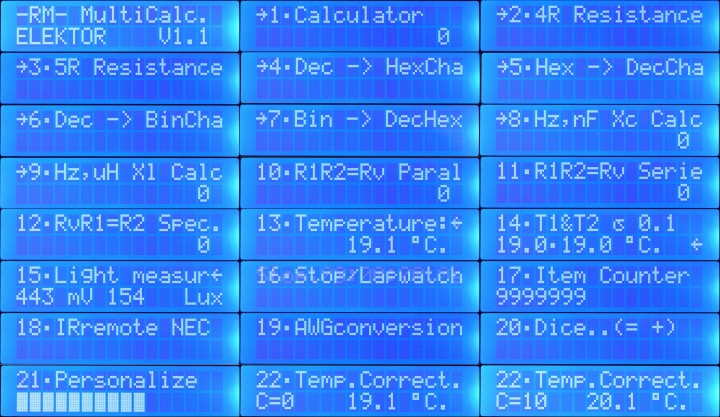
Fig. 9. Startup message and all 22 modes (message when selected) of the MultiCalculator.
Bill of Materials, contents of the kit
Resistor
R1,R2,R3,R4,R5,R7,R9,R10,R11,R14 = 10 kΩ, 167 mW, 1 %., body 1.9 x 3.4 mm
R6,R12 = 100 Ω, 250 mW, 1%, body 2 x 3.5 mm
R8,R13 = 1 kΩ, 167 mW, 1 %, body 1.9 x 3.4 mm
R15 = LDR GL5516, 5.4 x 4.4 mm, lead spacing 3.4 mm
R16 = NTC 10 kΩ, type 3950, 5% 10 kΩ
R17 = not needed
Capacitor
C1 = 100 nF, 50 V, 10 %, X7R, lead spacing 2.5 mm
C2,C3 = 10 µF, 25 V, 10 %, tantalum, lead spacing 2.5 mm
Semiconductor
D1,D2 = 1N4148, DO-35
LED = 3 mm (T1) LED, red
Q1 = KSA708YBU, TO-92
Q2 = 2N3904, TO-92
U1 = Mini Pro (ATmega328P, 5 V, 16 MHz)
U2 = TSOP14438
LCD1 = LCD module 16 x 2, Alphanumeric, 36 x 80 mm
Other
J1 = USB-C socket, chassis mounted, wired (5 V power supply only), 9 x 16 mm
J2 = 3.5 mm headphone jack, PCB mount PJ-325M (5 pins connections, 2 switched contacts)
H1 = 6way female header, right angle, pitch 2.54 mm
H2 = not needed
P1 = not needed
SW1-SW20 = 12x12x7.3mm Tactile Switches
SW1-SW20 = Keytop + clear cap for switches (cap is 11.8 mm square)
LCD1 = 16way male pin header, height 18.54 mm, pitch 2.54 mm, vertical
LCD1 = 16way socket, pitch 2.54 mm, vertical
FT232 Pro Mini USB-C TTL Adaptor (with 3 pin 3.3V/5V selection)
U1 = 12way pin header, vertical, pitch 2.54 mm (for Mini Pro)
2 x NTC 10 kΩ, Waterproof Temperature Sensor type 3950 10K, 1 m cable
3.5 mm plug
USB-A to USB-C cable, 1 m
Enclosure
4 x screw, M2, 12 mm, steel
4 x spacer sleeve, cylindrical, L: 3mm, Øout: 5mm, polyamide
4 x nut, M2, steel
8 x washer, M2, D=5mm, H=0.3mm, polyamide
4 x screw, M3, 6 mm, steel
4 x washer, M3, D=7mm, H=0.5mm, polyamide
4 x standoff, M3, Female-Female, Øout: 6mm L:8 mm, polyamide
4 x screw, M3, 10 mm, Head: countersunk, hex (Allen) key, HEX 2mm, steel
4 x screw, M3, 12 mm, Head: countersunk, hex (Allen) key, HEX 2mm, steel
4 x nut, M3, Plating: black finish, H: 2.4mm, steel
4 x self-adhesive foot; H: 3.8mm, transparent, polyurethane
6 panels made of 3 mm extruded acrylic transparent/clear sheet:
back panel, front panel, bottom panel, 2 side panels, U-shaped keyboard support panel
2 display support panels made of 5 mm extruded acrylic transparent/clear sheet
3 panels made of 3 mm cast acrylic umbra transparent sheet (dark brown):
display bezel, small support for display bezel, keyboard panel
Misc.
PCB 220684-1 v1.0
PCB
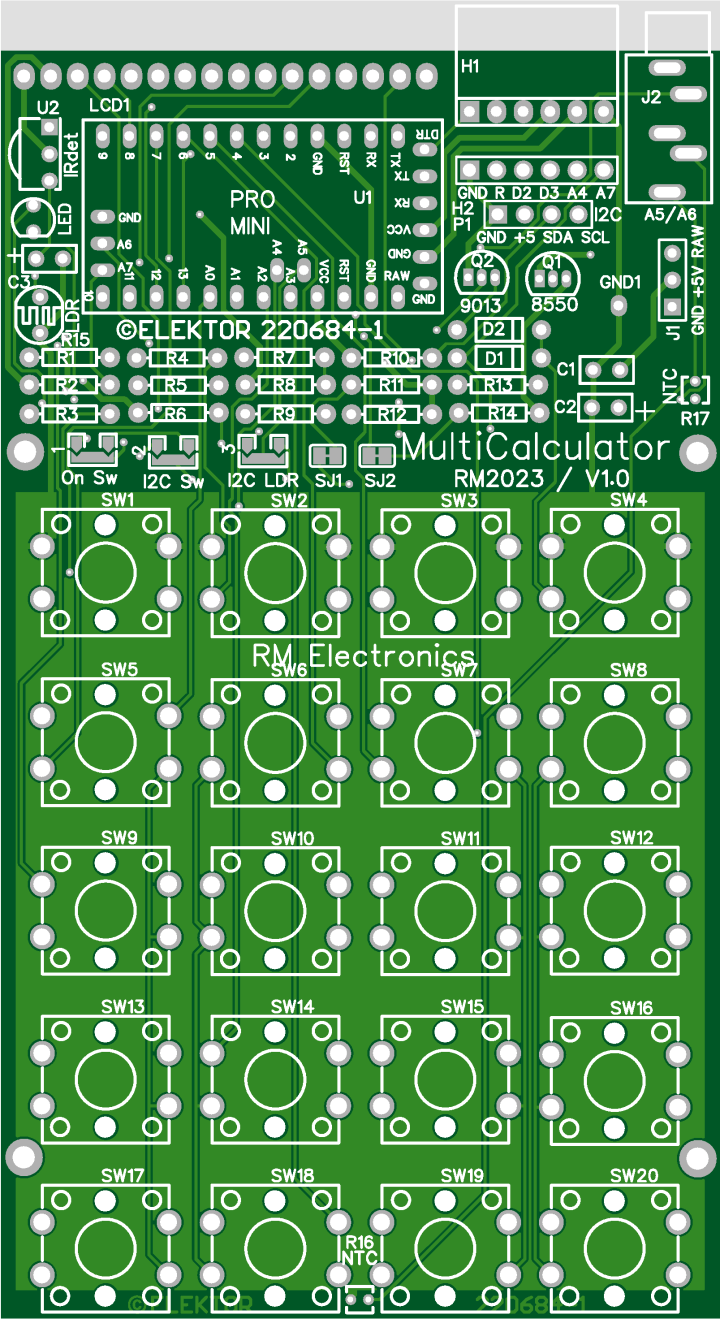
Fig. 10. Top overlay of PCB 220684-1 v1.0 of the MultiCalculator
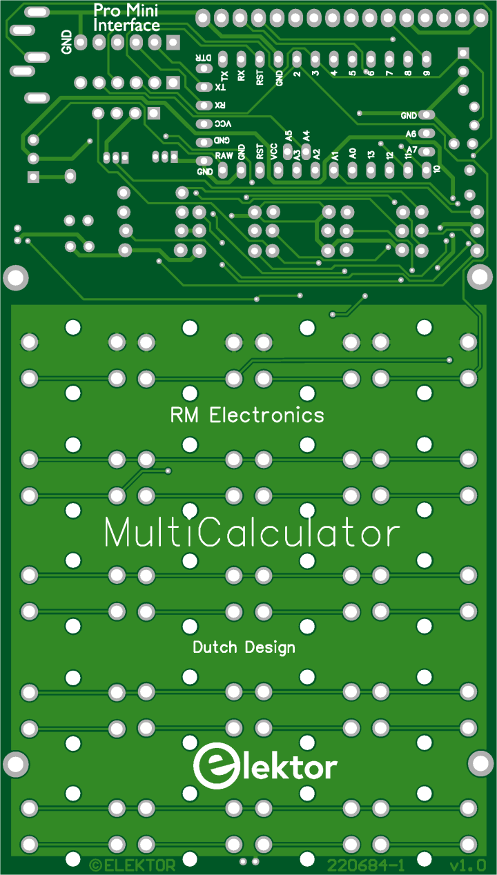 Fig. 11. Bottom overlay of PCB 220684-1 v1.0 of the MultiCalculator
Schematic
Fig.1. Schematic of the MultiCalculator
The MultiCalculator is built around a Pro Mini and is programmable, even after the construction is finished, through a 6way female header at the back. The software is bilingual, the menu language can be Dutch or English. Power supply voltage is 5 V, supplied via a USB-C plug at the back. Current is around 30mA. The design can also be used for other functions (using custom software) and can be programmed via the Arduino IDE. The serial ports have been kept free for monitoring or other functions. There are extra connections on the PCB, e.g.: GND, Reset, D2, D3, A4, A7 (connector H2, not used/fitted in the MultiCalculator). An I2C connection is available (connector P1, also not used/fitted in the MultiCalculator). To use I2C however, the required soldering bridges must be soldered then. Disabling via software is not possible with I2C enabled: dual-solder bridge 2 (I2C/Sw) next to R6 for SDA (A4) and dual-solder bridge 3 (I2C/LDR) next to R9 for SCL (A5). Only one solder bridge must be soldered of each dual-solder bridge on the PCB! The Pro Mini module only has so many I/O ports available. I/O ports A5 and A6 are available on the 3.5mm jack J2, connected by a track in solder bridges SJ1 and SJ2 to pullup resistors of 10kΩ (R11 and R14 respectively). These I/O ports can be used for temperature measurements or other applications (depending on the software). To sever the connections to these pull-up resistors cut the small track between the pads of SJ1 and SJ2. If the connection needs to be restored make a solder bridge between the adjacent pads. The LDR and NTC sensors are always connected to ground, and A5 (LDR/NTC) and A6 (NTC) respectively. On the PCB an NTC can be placed in two locations, R16 or R17. The two connections of R16 and R17 are connected in parallel so only 1 NTC must be mounted! Use R16 and leave R17 unmounted. R16 is farthest away from de module (should it get warm).
An analog input port is used to read switches SW2, SW3, SW4 by changing resistance through the selection of taps of series connection R2 (via D1), R3 and R4. SW2, SW3 are only used to a limited extent in the software. SW5 to SW20 are connected in a matrix. SW1 is used to change the mode of the MultiCalculator and is connected to a separate I/O port (D2). By pressing the MODE switch, the next mode of operation can be chosen. By pressing the mode button longer, the previous mode is chosen. In version 1.1 of the software 22 modes of operation are available.
SW4 is used to turn the MultiCalculator ON or OFF by software, depending on dual-solder bridge 1 next to R3 (On/Sw). If the solder bridge ON is made the MultiCalculator is always powered as soon as 5 V is supplied through the USB-C connector. If solder bridge Sw is made pressing SW4 will turn PNP transistor Q1 ON. It will pull R1 to ground via D2, the power supply is connected to the circuit and the module starts. SW4 must be pushed long enough for the module to make I/O port A4 high. Q1 is turned on through R5 and NPN transistor Q2. If A4 is low the MultiCalculator is switched OFF. The calculator can also be supplied with a voltage of 6-12 volt through the RAW connection on the PCB (J1). A small 5 V voltage regulator is part of the power supply circuit of the Pro Mini module. Switching ON is done by pressing the ON/AC button SW4 for a few seconds until text appears on the display. Switching OFF is done by pressing the ON button for more than 4 seconds. When the key is released, the MultiCalculator is turned off.
Originally the author used a SS8550 for PNP transistor Q1 and a 2SC9013 for NPN transistor Q2 as is indicated on the PCB. Due to availability these were replaced by types KSA708YBU and 2N3904. The exact type is not that critical but if a replacement is necessary pay attention to the pin order of the transistors. The types mentioned here have a different pin order than for instance types BC547 or BC337!
Programming the Arduino Pro Mini can be done via a USB-C to TTL converter (part of the kit). Make sure the jumper on the programming adapter is placed in the 5V position.
The custom enclosure is made of a total of 11 separate transparent acrylic panels. The top panels are dark brown transparent acrylic panels, the rest are clear. A USB-C connector is used connect a 5 V power supply.
Differential temperature measurement.
One mode of operation is not fully clarified in the user manual. To use the differential temperature measurement mode the cable of both waterproof sensors in the kit must be soldered to 3.5 mm plug (also in the kit). The plug can then be inserted in the 3.5 mm jack in the back of the MultiCalculator.
Fig. 2. The waterproof sensors as supplied in the kit
Cut off the connectors from the cables of the waterproof sensors. Each sensor should be soldered to the GND terminal of the 3.5 mm plug and the other wire of each sensor to one of the other contacts of the plug. Best is to cut the ground wires a few mm shorter so the other two are a bit longer and can each be soldered to one of the other 2 contacts of the 3.5 mm plug without having to bend the wires. The plug in the kit can be different than the one shown in the photo. Before soldering don’t forget to place the shell of the 3.5 mm plug over the cables of the sensors first. The plug in the kit can be different from the one shown in the photo.
Fig. 3. 2 Waterproof sensors connected to the 3.5 mm plug
Measurements using the waterproof sensors are a bit slow because the NTC is place in a epoxy filled 5 x 25 mm round metal tube. Operating temperature of these sensors is -40 to +85 °C.
Details on construction and a description of all modes of operation can be found in the ‘Construction and User Manual’ (can be downloaded at www.elektor.com). Following photo’s give an impression
Fig. 4. All parts except the LCD fitted.
A 18.5 mm long pin header must be soldered to the display under an angle. Nothing is bent!
Fig. 5. The header soldered to the display
The USB-C connector must be mounted in the back panel before its wires can be soldered to the PCB.
Fig. 6. Detail of back panel, display support with screws and M2 screw of the PCB.
Fig.7. Back of the finished MultiCalculator.
Fig. 8 The MultiCalculator is ready.
Specifications/properties
Power supply voltage 5V (USB-C)
Power supply current ≈ 28…32 mA
ProMini microcontroller module (ATmega328/5V/16MHz)
Programmable by the Arduino IDE (6way female pin header)
2x16 alpha-numerical LCD (LCD 1602, display color blue, white text)
20 labeled pushbuttons
3.5 mm jack to connect external sensors
Operating temperature of waterproof sensors -40 to +85 °C.
22 Menus (software version 1.1)
Functions:
- Decimal floating-point calculation.
- Binary, hexadecimal, decimal calculation, ASCII character viewer.
- Temperature and delta T. measurement
- Stopwatch with lap time.
- Decoder resistors codes.
- Reactance calculation for capacitors (Xc) and coils (Xl).
- Resistance parallel, series and supplement resistance calculation.
- Light measurement in mV and Lux.
- Item counter.
- IR decoder for NEC codes.
- AWG calculation with Maximum current calculation.
- Dice with roll simulation.
- Personalize startup message.
- Calibration of the temperature measurement (zero point correction).
Modes of operation (software v1.1)
1 – Calculator
2 – 4 Ring Resistor Code
3 – 5 Ring Resistor Code
4 – Decimal to Hexadecimal and Character (ASCII) conversion
5 – Hexadecimal to Decimal and Character (ASCII) conversion
6 – Decimal to Binary and Character (ASCII) conversion
7 – Binary to Decimal and Hexadecimal conversion
8 – Hz, nF, reactance Xc calculation
9 – Hz, µH, reactance Xl calculation
10 – Resistance calculation of two resistors connected in parallel
11 – Resistance calculation of two resistors connected in series
12 – Calculation unknown parallel resistor
13 – Temperature measurement
14 – Differential temperature measurement T1&T2 and Delta (δ)
15 – Light measurement
16 – Stopwatch with lap time function
17 – Item counter
18 – Display IR NEC code from a remote control
19 – AWG conversion (American Wire Gauge)
20 – Rolling Dice
21 – Personalize startup message
22 – Temperature calibration
Fig. 9. Startup message and all 22 modes (message when selected) of the MultiCalculator.
Bill of Materials, contents of the kit
Resistor
R1,R2,R3,R4,R5,R7,R9,R10,R11,R14 = 10 kΩ, 167 mW, 1 %., body 1.9 x 3.4 mm
R6,R12 = 100 Ω, 250 mW, 1%, body 2 x 3.5 mm
R8,R13 = 1 kΩ, 167 mW, 1 %, body 1.9 x 3.4 mm
R15 = LDR GL5516, 5.4 x 4.4 mm, lead spacing 3.4 mm
R16 = NTC 10 kΩ, type 3950, 5% 10 kΩ
R17 = not needed
Capacitor
C1 = 100 nF, 50 V, 10 %, X7R, lead spacing 2.5 mm
C2,C3 = 10 µF, 25 V, 10 %, tantalum, lead spacing 2.5 mm
Semiconductor
D1,D2 = 1N4148, DO-35
LED = 3 mm (T1) LED, red
Q1 = KSA708YBU, TO-92
Q2 = 2N3904, TO-92
U1 = Mini Pro (ATmega328P, 5 V, 16 MHz)
U2 = TSOP14438
LCD1 = LCD module 16 x 2, Alphanumeric, 36 x 80 mm
Other
J1 = USB-C socket, chassis mounted, wired (5 V power supply only), 9 x 16 mm
J2 = 3.5 mm headphone jack, PCB mount PJ-325M (5 pins connections, 2 switched contacts)
H1 = 6way female header, right angle, pitch 2.54 mm
H2 = not needed
P1 = not needed
SW1-SW20 = 12x12x7.3mm Tactile Switches
SW1-SW20 = Keytop + clear cap for switches (cap is 11.8 mm square)
LCD1 = 16way male pin header, height 18.54 mm, pitch 2.54 mm, vertical
LCD1 = 16way socket, pitch 2.54 mm, vertical
FT232 Pro Mini USB-C TTL Adaptor (with 3 pin 3.3V/5V selection)
U1 = 12way pin header, vertical, pitch 2.54 mm (for Mini Pro)
2 x NTC 10 kΩ, Waterproof Temperature Sensor type 3950 10K, 1 m cable
3.5 mm plug
USB-A to USB-C cable, 1 m
Enclosure
4 x screw, M2, 12 mm, steel
4 x spacer sleeve, cylindrical, L: 3mm, Øout: 5mm, polyamide
4 x nut, M2, steel
8 x washer, M2, D=5mm, H=0.3mm, polyamide
4 x screw, M3, 6 mm, steel
4 x washer, M3, D=7mm, H=0.5mm, polyamide
4 x standoff, M3, Female-Female, Øout: 6mm L:8 mm, polyamide
4 x screw, M3, 10 mm, Head: countersunk, hex (Allen) key, HEX 2mm, steel
4 x screw, M3, 12 mm, Head: countersunk, hex (Allen) key, HEX 2mm, steel
4 x nut, M3, Plating: black finish, H: 2.4mm, steel
4 x self-adhesive foot; H: 3.8mm, transparent, polyurethane
6 panels made of 3 mm extruded acrylic transparent/clear sheet:
back panel, front panel, bottom panel, 2 side panels, U-shaped keyboard support panel
2 display support panels made of 5 mm extruded acrylic transparent/clear sheet
3 panels made of 3 mm cast acrylic umbra transparent sheet (dark brown):
display bezel, small support for display bezel, keyboard panel
Misc.
PCB 220684-1 v1.0
PCB
Fig. 10. Top overlay of PCB 220684-1 v1.0 of the MultiCalculator
Fig. 11. Bottom overlay of PCB 220684-1 v1.0 of the MultiCalculator
Discussion (17 commentaire(s))