
LoRa Wearable Patient Monitor
This is a POC of an IoT wearable device to monitor patient oximetry, heart and respiration rate, temperature and movement, and estimate overall condition. The device could perform simpler calculations on site (edge computing) and further processing could be done remotely on the cloud with data transmitted via LoRa.
For a better reading experience, please refer to my GitHub page: https://github.com/MechatronixLab/WPM
This project is Open Source, licensed under the MIT license.
WEARABLE PATIENT MONITOR
This work is a proof of concept for a connected wearable patient monitor capable of measuring oximetry parameters, body temperature and track the patient's movement, while transmitting data wirelessly via LoRa communication.
It is based on the Nucleo WL55JC1 development board, based on the STM32WL55JC, from ST Microelectronics, a Maxim (now Analog Devices) MAX30102 pulse oximetry sensor, a Würth Elektronik WSEN-ISDS 6-Axis IMU, an OLED display and a Piezoelectric buzzer for simple audio generation.
The device features LoRa connection, allowing it to be used in remote locations where telecommunications infrastructure is not well established.
⚠️ DISCLAIMER ⚠️
THIS IS NOT A MEDICAL DEVICE!
Putting a medical device on the market is no joke! It involves severe testing, documentation and certification.
The device presented here is a benchtop prototype developed for learning purposes only. This prototype was not designed or tested for electrical safety and electromagnetic compatibility, nor went through clinical trials.
DO NOT TAKE MEDICAL DECISIONS BASED ON MEASUREMENTS TAKEN BY THIS DEVICE!
MOTIVATION
Many patients in need of medical assistance could be treated more comfortably at home, but monitoring their condition in a timely manner could be a challenge, especially if they live in rural areas.
The goal of this project is to develop a low power, wirelessly connected, wearable device to monitor patient heart rate, oximetry, respiration rate, temperature and estimate overall condition. The device would include a microcontroller that manages sensors (such as optical, thermal, inertial, etc.) and connects to an IoT network such as LoRaWAN. A rechargeable battery would also be present, as well as the corresponding power management IC.
The NUCLEO-WL55JC would be a great platform for prototyping such device, since it provides the sub-GHz radio and full access to the MCU pins. Sensors and other hardware parts can be integrated using I2C and SPI communication, and are generally available in breakout boards for easy development.
This kind of device enables caregivers and physicians to monitor their patients remotely and gather information continuously. The data collected can also be processed autonomously using AI to detect potential degradation of patient’s condition and triggering alarms, while simpler analysis could be done directly by the IoT device (edge computing).
The benefits of the device go beyond patient’s health. The overall treatment cost could be lowered since caregivers and physicians could focus attention on the most critical patients more often, and more stable patients can be visited more sporadically.
This idea was submitted to the STM32 Wireless Innovation Design Contest, promoted by Elektor Magazine and ST Microelectronics. They kindly provided a NUCLEO-WL55JC board, free of charge. Thank you!
HARDWAREHARDWARE BLOCK DIAGRAM
[Image 01.png]
BENCHTOP PROTOTYPE
[Image 02.png]
The image below highlights the main parts of the hardware (from right to left):
[Image 03.png]
The sensors and display are all controlled by the MCU via the same I2C bus. The buzzer is driven by a PWM signal with tone frequency of 4 kHz.
Connections (CubeMX):
[Image 04.png]
Pinout table for connection between the Nucleo board (Nucleo WL55JC1 schematic) and other components on the breadboard:
Nucleo WL55JC1 / MCU Pin / Peripheral / Signal
CN7 Pin 16 / VDD / - / +3.3V
CN7 Pin 18 / - / - / +5.0V
CN7 Pin 20 / VSS / - / GND
CN7 Pin 22 / VSS / - / GND
CN7 Pin 28 / PB1 / GPIO / OLED_RESET
CN7 Pin 36 / PB14 / I2C3 SDA / I2C SDA
CN7 Pin 38 / PB13 / I2C3 SCL / I2C SCL
CN10 Pin 16 / PA8 / TIM1 CH1 PWM Out / BUZZER
LoRa RECEIVER
A very simple LoRa receiver was assembled using a LoRa module from G-NiceRF, which is based on the SX1276 chip from Semtech, and a Blue Pill board, which is based on the ST Microelectronics STM32F103C6.
The software running on the BluePill is a slightly modified version of arduino-LoRa-STM32 that was developed by ARMtronix Technologies.
LoRa module:
[Image 05.png]
More information about how to make this receiver can be found on this video and arcticle from How To Electronics.
Receiver:
[Image 06.png]
The software modifications made were necessary to match the radio configurations on the STM32WL55:
BLUE PILL (STM32F103C6) / SX1276 MODULE / FTDI MODULE
GND / GND / GND
+3.3V / VCC / VCC
PA4 / NSS / -
PA1 / DIO0 / -
PA5 / SCK / -
PA6 / MISO / -
PA7 / MOSI / -
PA9 / - / RX
PA10 / - / TX
PB0 / RST / -
SOFTWARE
SOFTWARE BLOCK DIAGRAM
[Image 07.png]
INITIALIZATION
As the software starts, 3 opening screens are shown:
Project Title:
[Image 08.png]
Software Version:
[Image 09.png]
Elektor/ST Contest information:
[Image 10.png]
The device also prints data via its serial port. After initialization information, the device continuously transmits raw data from sensors at a rate of 30 Hz. This transmission can only be done while the USB cable is connected to the Nucleo board, so it is available mainly for development and debugging purposes.
Data is sent via LoRa at a rate of 1 Hz.
Console:
[Image 11.png]
MEASUREMENTS
The patient should place their finger over the MAX30102 sensor to get oximetry measurements.
The following parameters are present:
Working oximetry measurements:
[Image 12.png]
Using the Serial Oscilloscope tool from x-io Technologies, it is possible to plot the raw data transmitted from the prototype in real time:
Gyroscope raw data:
[Image 13.png]
Accelerometer raw data:
[Image 14.png]
Oximetry raw data:
[Image 15.png]
LoRa RECEIVER
The receiver simply relays data from the LoRa module to the UART, which is then converted to USB and captured by a computer.
Data received via LoRa:
[Image 16.png]
Code organization
Code is organized according to the following layered architecture diagram.
Layered architecture software diagram:
[wpm-wl55-layered-diagram.png]
The idea is that each block in the diagram corresponds to a pair of .c/.h files that are loosely coupled, so the interfaces of libraries occur only in the vertical direction, and only one layer at a time. However, since the code is still in development, there are a few exceptions to this guideline throughout the code. Data is manipulated between layers using structures and pointers.
Sub-GHz module
The most complex part of the project was to get the Sub-GHz module working correctly. Most of the examples available on the CubeMX package rely on a scheduler that uses function pointers and is not trivial to understand. Additionally, most examples demand two Nucleo boards, and this project had only one available. Therefore, a simpler approach was used by configuring the Sub-GHz module using the Low Lever drivers. This arcticle detais the procedure on how to set the radio correctly, and was used as base for starting software development. All other modules were added upon this foundation.
SIGNAL PROCESSING
One of the most interesting part of this project was dealing with the raw data coming from the red and infrared LEDs present on the oximetry sensor.
In order to obtain the peripheral oxygen saturation value, the algorithm detailed on this application note from Maxim. Another great resource about this topic is this one from Texas Instruments.
The basic idea is to get the DC and AC component from both red and infrared signals, then obtain the "Ratio of Ratios" and use it in a linear regression to finally get an approximate SpO2 value. This obviously leads to deviations from the real oxygen saturation of the patient, but this simplification is reasonable for this POC.
Raw signal with DC and AC components; Linear regression using the Ratio of Ratios:
[signal-processing.png]
A series of circular buffers were used to calculate the moving average of the two signals, to get DC values and the RMS calculation was used to obtain the AC values.
To get the heart rate, the derivative of the red signal in respect to time is used, and since the negative parts of the derivative are more abrupt, they were used to signal a heartbeat detection. Again, circular buffer were used to get moving averages of beats for a number of samples, and then the heart rate in beats per minute is calculated.
PROTOTYPE PERFORMANCE
In order to evaluate the performance of the oximetry, measurements were taken by the WPM prototype and a commercially available pulse oximeter, simultaneously. Results showed good coherence between the two devices.
Comparison between WPM and a commercial pulse oximeter:
[image-17.png]
ACKNOWLEDGEMENTS
My lovely wife and kids, for their everlasting support ❤️
Karine Moriya and everyone @ J.G. Moriya
Elecia White and everyone @ Classpert
Fabio Souza and Halysson Jr @ Franzininho
William Maia and Daniel Botelho @ ST Microelectronics Brazil
Fabio Costa and Érico Hassegawa @ Würth Elektronik Brazil
Maristone Gomes, Gabriel de Benevides and Fernando Júdice @ Salvus
Matt Mielke @ DigiKey, for writing this arcticle explaining how to use the Sub-GHz module on the STM32WL55
Elektor Magazine and ST Microelectronics, for promoting the STM32 Wireless Innovation Design Contest
This project is Open Source, licensed under the MIT license.
WEARABLE PATIENT MONITOR
This work is a proof of concept for a connected wearable patient monitor capable of measuring oximetry parameters, body temperature and track the patient's movement, while transmitting data wirelessly via LoRa communication.
It is based on the Nucleo WL55JC1 development board, based on the STM32WL55JC, from ST Microelectronics, a Maxim (now Analog Devices) MAX30102 pulse oximetry sensor, a Würth Elektronik WSEN-ISDS 6-Axis IMU, an OLED display and a Piezoelectric buzzer for simple audio generation.
The device features LoRa connection, allowing it to be used in remote locations where telecommunications infrastructure is not well established.
⚠️ DISCLAIMER ⚠️
THIS IS NOT A MEDICAL DEVICE!
Putting a medical device on the market is no joke! It involves severe testing, documentation and certification.
The device presented here is a benchtop prototype developed for learning purposes only. This prototype was not designed or tested for electrical safety and electromagnetic compatibility, nor went through clinical trials.
DO NOT TAKE MEDICAL DECISIONS BASED ON MEASUREMENTS TAKEN BY THIS DEVICE!
MOTIVATION
Many patients in need of medical assistance could be treated more comfortably at home, but monitoring their condition in a timely manner could be a challenge, especially if they live in rural areas.
The goal of this project is to develop a low power, wirelessly connected, wearable device to monitor patient heart rate, oximetry, respiration rate, temperature and estimate overall condition. The device would include a microcontroller that manages sensors (such as optical, thermal, inertial, etc.) and connects to an IoT network such as LoRaWAN. A rechargeable battery would also be present, as well as the corresponding power management IC.
The NUCLEO-WL55JC would be a great platform for prototyping such device, since it provides the sub-GHz radio and full access to the MCU pins. Sensors and other hardware parts can be integrated using I2C and SPI communication, and are generally available in breakout boards for easy development.
This kind of device enables caregivers and physicians to monitor their patients remotely and gather information continuously. The data collected can also be processed autonomously using AI to detect potential degradation of patient’s condition and triggering alarms, while simpler analysis could be done directly by the IoT device (edge computing).
The benefits of the device go beyond patient’s health. The overall treatment cost could be lowered since caregivers and physicians could focus attention on the most critical patients more often, and more stable patients can be visited more sporadically.
This idea was submitted to the STM32 Wireless Innovation Design Contest, promoted by Elektor Magazine and ST Microelectronics. They kindly provided a NUCLEO-WL55JC board, free of charge. Thank you!
HARDWAREHARDWARE BLOCK DIAGRAM
[Image 01.png]
BENCHTOP PROTOTYPE
[Image 02.png]
The image below highlights the main parts of the hardware (from right to left):
- Nucleo board
- Piezoelectric buzzer
- MAX30102 breakout board
- OLED display (monochrome, 128 x 64 pixels)
- WSEN-EVAL ISDS breakout board
- Voltage regulators (+5.0V and +3.3V)
[Image 03.png]
The sensors and display are all controlled by the MCU via the same I2C bus. The buzzer is driven by a PWM signal with tone frequency of 4 kHz.
Connections (CubeMX):
[Image 04.png]
Pinout table for connection between the Nucleo board (Nucleo WL55JC1 schematic) and other components on the breadboard:
Nucleo WL55JC1 / MCU Pin / Peripheral / Signal
CN7 Pin 16 / VDD / - / +3.3V
CN7 Pin 18 / - / - / +5.0V
CN7 Pin 20 / VSS / - / GND
CN7 Pin 22 / VSS / - / GND
CN7 Pin 28 / PB1 / GPIO / OLED_RESET
CN7 Pin 36 / PB14 / I2C3 SDA / I2C SDA
CN7 Pin 38 / PB13 / I2C3 SCL / I2C SCL
CN10 Pin 16 / PA8 / TIM1 CH1 PWM Out / BUZZER
LoRa RECEIVER
A very simple LoRa receiver was assembled using a LoRa module from G-NiceRF, which is based on the SX1276 chip from Semtech, and a Blue Pill board, which is based on the ST Microelectronics STM32F103C6.
The software running on the BluePill is a slightly modified version of arduino-LoRa-STM32 that was developed by ARMtronix Technologies.
LoRa module:
[Image 05.png]
More information about how to make this receiver can be found on this video and arcticle from How To Electronics.
Receiver:
[Image 06.png]
The software modifications made were necessary to match the radio configurations on the STM32WL55:
- Frequency: 915 MHz
- Bandwidth: 500 kHz
- Spreading Factor: 11Pinout connections for LoRa receiver (white cable of previous image is not connected):
BLUE PILL (STM32F103C6) / SX1276 MODULE / FTDI MODULE
GND / GND / GND
+3.3V / VCC / VCC
PA4 / NSS / -
PA1 / DIO0 / -
PA5 / SCK / -
PA6 / MISO / -
PA7 / MOSI / -
PA9 / - / RX
PA10 / - / TX
PB0 / RST / -
SOFTWARE
SOFTWARE BLOCK DIAGRAM
[Image 07.png]
INITIALIZATION
As the software starts, 3 opening screens are shown:
Project Title:
[Image 08.png]
Software Version:
[Image 09.png]
Elektor/ST Contest information:
[Image 10.png]
The device also prints data via its serial port. After initialization information, the device continuously transmits raw data from sensors at a rate of 30 Hz. This transmission can only be done while the USB cable is connected to the Nucleo board, so it is available mainly for development and debugging purposes.
Data is sent via LoRa at a rate of 1 Hz.
Console:
[Image 11.png]
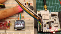
MEASUREMENTS
The patient should place their finger over the MAX30102 sensor to get oximetry measurements.
The following parameters are present:
- SpO2: Peripheral Saturation of Oxygen (%)
- PInd: Perfusion Index (%)
- HR: Heart rate (beats per minute)
- T: Finger temperature (°C)
Working oximetry measurements:
[Image 12.png]
Using the Serial Oscilloscope tool from x-io Technologies, it is possible to plot the raw data transmitted from the prototype in real time:
Gyroscope raw data:
[Image 13.png]
Accelerometer raw data:
[Image 14.png]
Oximetry raw data:
[Image 15.png]
LoRa RECEIVER
The receiver simply relays data from the LoRa module to the UART, which is then converted to USB and captured by a computer.
Data received via LoRa:
[Image 16.png]
Code organization
Code is organized according to the following layered architecture diagram.
Layered architecture software diagram:
[wpm-wl55-layered-diagram.png]
The idea is that each block in the diagram corresponds to a pair of .c/.h files that are loosely coupled, so the interfaces of libraries occur only in the vertical direction, and only one layer at a time. However, since the code is still in development, there are a few exceptions to this guideline throughout the code. Data is manipulated between layers using structures and pointers.
Sub-GHz module
The most complex part of the project was to get the Sub-GHz module working correctly. Most of the examples available on the CubeMX package rely on a scheduler that uses function pointers and is not trivial to understand. Additionally, most examples demand two Nucleo boards, and this project had only one available. Therefore, a simpler approach was used by configuring the Sub-GHz module using the Low Lever drivers. This arcticle detais the procedure on how to set the radio correctly, and was used as base for starting software development. All other modules were added upon this foundation.
SIGNAL PROCESSING
One of the most interesting part of this project was dealing with the raw data coming from the red and infrared LEDs present on the oximetry sensor.
In order to obtain the peripheral oxygen saturation value, the algorithm detailed on this application note from Maxim. Another great resource about this topic is this one from Texas Instruments.
The basic idea is to get the DC and AC component from both red and infrared signals, then obtain the "Ratio of Ratios" and use it in a linear regression to finally get an approximate SpO2 value. This obviously leads to deviations from the real oxygen saturation of the patient, but this simplification is reasonable for this POC.
Raw signal with DC and AC components; Linear regression using the Ratio of Ratios:
[signal-processing.png]
A series of circular buffers were used to calculate the moving average of the two signals, to get DC values and the RMS calculation was used to obtain the AC values.
To get the heart rate, the derivative of the red signal in respect to time is used, and since the negative parts of the derivative are more abrupt, they were used to signal a heartbeat detection. Again, circular buffer were used to get moving averages of beats for a number of samples, and then the heart rate in beats per minute is calculated.
PROTOTYPE PERFORMANCE
In order to evaluate the performance of the oximetry, measurements were taken by the WPM prototype and a commercially available pulse oximeter, simultaneously. Results showed good coherence between the two devices.
Comparison between WPM and a commercial pulse oximeter:
[image-17.png]
ACKNOWLEDGEMENTS
My lovely wife and kids, for their everlasting support ❤️
Karine Moriya and everyone @ J.G. Moriya
Elecia White and everyone @ Classpert
Fabio Souza and Halysson Jr @ Franzininho
William Maia and Daniel Botelho @ ST Microelectronics Brazil
Fabio Costa and Érico Hassegawa @ Würth Elektronik Brazil
Maristone Gomes, Gabriel de Benevides and Fernando Júdice @ Salvus
Matt Mielke @ DigiKey, for writing this arcticle explaining how to use the Sub-GHz module on the STM32WL55
Elektor Magazine and ST Microelectronics, for promoting the STM32 Wireless Innovation Design Contest
Mises à jour de l'auteur