
Nixie bargraph thermometer with Arduino
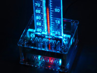
This USB powered thermometer based on an Arduino Nano shows the temperature using a vintage Russian "nixie" style IN-9 bargraph tube.
Besides the well known numerical nixie tubes, other types of neon filled tubes were also used in the past for specific applications. For linear gauge displays, neon filled bargraph tubes were used. The most prevalent types of these tubes are the Russian IN-9 and IN-13 linear indicators. These tubes are technically not nixie tubes as they do not show digits but they were used during the same time period and they share the same warm vintage look.
Most of the "nixie" thermometer kits on the market are based on the IN-13 bargraph tube. Compared to the IN-13 tube, the IN-9 is quite unpopular as many people run into problems when they try to use them in their projects. An IN-9 tube consists of a nickel plated anode mesh and cathode of molybdenum wire. Due to the use of molybdenum, the ignition voltage of the neon gas mixture in the tube remains quite low (< 140 V). At the bottom the molybdenum wire is coated with zirconium which has an even lower ignition voltage. As a result the bargraph column tends to start at the bottom.
Opposed to the IN-9 tube, the IN-13 tube uses an auxiliary cathode to make sure the glow starts at the bottom. As IN-13 tube stocks become more and more depleted we had no other option than to use the IN-9 tube.
The two main problems with this tube are the bargraph display not starting at the bottom (column breaks) and cathode poisoning where the bargraph display cannot reach the end of the tube. The cathode poisoning problem can in most cases be solved by a burn-in procedure where the tube is subjected to overcurrent until the glow reaches the end of the tube. The other issue is a lot more trickier...
Originally, IN-9 tubes were used for indicating mains voltages and currents or similar voltages and were often driven with half-wave rectified current instead of DC. There was a discussion about this on the NeoNixie newsgroup and there was even a schematic posted by user "Start End". The trick is to switch the tube on and off around 50 - 100 times per second. We did a lot of tests with this setup and it works remarkably well. The only drawback is that the linearity is not very good, but that can easily be corrected in software.
The complete thermometer circuit consists of a 5 V to 150 V "voltage doubler" step-up converter, an IN-9 tube driver based on a low voltage rail-to-rail opamp, two RGB leds and an Arduino Nano. We did choose a very cheap Chinese Arduino Nano clone. As such, there are no SMD parts to solder and for the price of the Arduino Nano we couldn't even supply a partially pre-assembled PCB with a microcontroller and a USB to serial converter IC.
The Arduino Nano switches the IN-9 tube on and off around 75 times a second, so the display does not show any flickering. To prevent cathode poisoning of the IN-9 tube, a sweep animation is displayed at an adjustable interval. The temperature sensor is a DS18B20. As the total power consumption is less than 1 W, the thermometer can even be powered via a standard USB port on a computer.
Discussion (5 commentaire(s))