Simulating oscillators can be problematic as they often won't start in the simulator. Here is a trick that might help you out.
Oscillators are difficult to simulate because often they won't start in the simulator. The problem is due to the simulator assuming an evironment without imperfections like noise and interference. Also, the component models are usually too simple; they are intended for simulating what they are supposed to do, not what they are not supposed to do. Adding disturbances to the simulation might help you out in such a case.
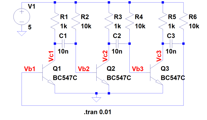
As an example let's look at this classic multivibrator circuit. Although I gave it three stages for fun -- commonly used for chasing or running (LED) light applications -- it is nothing special. Build this circuit on a breadboard and it will work just fine; run it in LTspice and nothing happens.
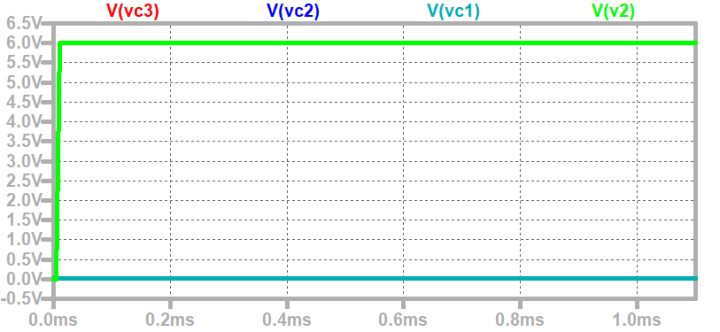
Build this circuit on a breadboard and it will work just fine; run it in LTspice and nothing happens. The problem is due to too much perfection, or, put in another way, lack of detail. All transistors are identical and so are the capacitors and resistors. The simulator will calculate the same state for every stage whereas in real life each stage will behave slightly differently. As a result, nothing happens in the simulator while the real-life circuit oscillates as intended (at around 5 kHz).
Note that this circuit may also fail to start in real life, but the chances that such a situation arises are slim.
Fooling around with slightly different component values or using equivalent but different transistor models may help but often at the expense of slowing down the simulator or very long start-up times. The inconvenience is, of course, that the simulated circuit no longer represents the real circuit, leading to confusion. Fiddling around also is time consuming.
What you do want is to inject a disturbance to get the oscillator started without influencing the circuit once it is running; a timed switch, for instance. Such a solution means adding a little circuit to the simulation, but by adding a comment it can be made clear what it is for.
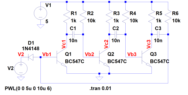
The multivibrator above can be kickstarted by keeping one stage disabled for a short time at startup. Once the other stages have reached a stable state, you release the disabled stage and away it goes. Add V2 and D1 to kickstart the multivibrator.
An easy way to do this is with a piece-wise linear (PWL) voltage source (V2). This is a normal voltage source, but configured through the 'Advanced' button. When configured properly it can produce a voltage step (or pulse) at a well-defined moment in time. The output of the voltage source can connect to the circuit through a diode (D1). With the anode of D1 disconnected from Vb1 the oscillator does not start in the simulator.
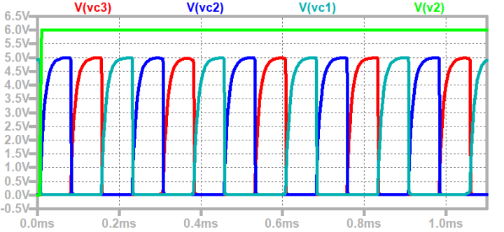
V2 produces a voltage step from 0 to 6 volts 5 microseconds after simulation start, effectively blocking Q1. When V2 has ramped up enough, D1 stops conducting and liberates Q1. This starts the oscillator and the circuit finally works as intended. The value of 6 volts was chosen rather arbitrarily; it must be such that the diode disconnects completely. Connect V2 through D1 to Vb1 and it works!
Note that the Spice directive '.startup' does not work here, probably because it ramps up everything at the same speed and in the same way; it doesn't introduce any randomness.
How to kickstart your oscillator simulation depends on its design. I've shown one method here, but there are others. The hard part is to find the sweet spot that unblocks the simulation.
The LTspice model shown here can be downloaded below.
Want to build a project?
Bring your design to life with the Elektor PCB Service, powered by Eurocircuits. Upload the project files and order professionally manufactured PCBs or assembled boards through a proven European production platform.
Supporting KiCad, Eagle, Gerber, and ODB++ formats, the service is suitable for everything from prototypes and validation builds to series production and volume manufacturing.
Veuillez saisir votre adresse électronique. Les instructions de réinitialisation de votre mot de passe vous seront immédiatement envoyées par courriel.
Elektor Magazine est depuis 65 ans l’une des principales sources d’information en électronique pour les ingénieurs, les concepteurs, les start-ups et les entreprises. Notre magazine est soutenu par une communauté active d’ingénieurs en électronique – des étudiants aux professionnels – passionnés par la conception et le partage d’idées innovantes.
Pour eux, nous publions chaque année des centaines de contenus sous différents formats, tels que des articles, des vidéos, des webinaires et d’autres formats d’apprentissage. Notre mission est de partager les connaissances de toutes les manières possibles et d’inspirer les lecteurs avec les dernières évolutions du secteur de l’ingénierie électrique.
Thank you for your vote!
Ajoutez vos commentaires
Thank you for your vote!
Veuillez vous connecter pour ajouter une note ou fermez pour revenir en arrière

Discussion (1 commentaire(s))