
Nixie compact, thermometer, clock GPS, letter box alarm:
This is the story of a Christmas gift for my father...He always like old things and nixies must be good for him. Like many people, I like this display, warm color.The original idea was to create only a thermometer, internal and external. For external, I wanted to have solar recharge, RF transmission. For internal, a traditional DS1820 to get the temperature.
This is the story of a Christmas gift for my father...
He always like old things and nixies must be good for him. Like many people, I like this display, warm color.
The original idea was to create only a thermometer, internal and external. For external, I wanted to have solar recharge, RF transmission. For internal, a traditional DS1820 to get the temperature.
Then, I remember that my parents has a letter box around 60m from the house. I thought that can be nice to display a LED blinking when there is a letter inside.
After some test, my lovely wife complained that the internal temperature was too high compare to the real room temperature. The nixie and so, warm too much the environment. So, I decided to do another RF module for internal but as there is no sunshine, can be charge directly from the main, but can be 6 months at least without charge.
At the end, with 2 digits on the top and 2 digits on the bottom, I think that to display also the time can be a good option. As I do not like button, I decided to use a GPS receiver to get the time. As the GPS is not always good inside, I add the option to integrate it inside the external solar power sensor.
So, the current status and feature of this product is:
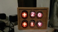
- Receiver nixie: * Display 2 times 2 digits plus symbol
- Can display by menu:
- Temperature internal and external
- Temperature external and external battery level, power by small standard solar panel
- To be develop the external humidity
- Number of events received from the letter box and battery level
- Display internal temperature and battery level
- Display Min and Max on rolling 24h of the external temperature
- Time - LED blinking with the number of events from the letter box. Reset during the night
- Switch off the nixie when night detected by LDR
- Dimmer of the Nixie brightness regarding the room light
- One button for the menu, one button to adjust the winter or summer time (time zone is estimated with the longitude)
- Use of RFM12 module and specific trame code for each different sensor
- time capture with GPS receiver. autoadjustment of the time when receive valid trame. If not, using internal clock. The internal clock can adapt itself for better accuracy when receive correct GPS time.
- Box with front view, compact, 14cm*8cm
Sensors:
- Can use solar panel the recharge Lithium battery. charger in discrete and very simple. Can work even with small solar panel and small current.
- Use a DS1820 for temperature capture. Need to add option for humidity
- Use an LDR to detect letter box open light. Special calibration mode with a speaker for each different letter box
- Configuration of the sensor for different option like send temperature or not, send trame monitoring over the air or not. configuration with DIP switch
- Can be recharge directly from main 220v/110v with small embedded module.
- Sensor in very small box, 7cm*5cm, transparent cover for internal solar panel.
- Can select frequency of the upload
- Very low consumption, 10uA with special 3.3V regulator
- Add the GPS receiver inside the external solar sensor. Look the latest comments for explanation.
So, at this moment, I have one receiver with 3 sensors, one for the letter box, one temperature internal and one for external. Both modules are using PIC18F2420. clock is different.
PCB are already done and under test for the receiver. For the sensor, done also. The PCB is compatible for the different option.
Christmas is coming. Need speed up now...
Update December 17th:
- First version finished for Christmas. Put all in a plastic box, make hole the the nixies and cover with wood like sticker
- GPS for time is so-so. Didn t work in several place inside. Plan to put it into the external sensor (PCB plan for it) but no time to implement it now. Next version.
- Put here some pictures with the last finishing, and the 3 sensors.
- Testing the receiver PCBA on going for new version
Update December 29th:
- Christmas gift is done. My father is happy. Some comments and future modifications:
- The range of the RFM12 was not good and cannot work with the 60m long for the letter box. I had to add 4cm on the antenna, both on emetter and receiver to make it work.
- I will build a repetitor for RFM later, solar powered. The external sensor with solar power works well. Battery always full.
- I'm building now based on the PCB and I made bad mistake on the implent. Forgot that the tubes glass was much bigger diameter than the pin. I have to put the tube support with some extension with 0 ohm.
- I'm using now some chinese version QS30 (cheap in China). I planned use again B5092 but I'm tired with the shop I bought them (German site "Ask Jan first"). For the first order, I didn t get what I paid for and when I tried to ask some information for a second order, often rude answer. Not polite attitude didn t deserve business... I do not recomment this seller. Any good website recommendation are welcome for nixies...
- QS30 need higher anode resistance (22K) and so far, not works well. The power supplier is good (180V) and more stable than on the mockup.
- The GPS works well but only close to a window. Really need to test the GPS embedded in the external sensor.
- Made some Sw modification for send the adjustment parameter of the letter box sensor on RF at each switch ON. can see the nominal value for the dark and the delta value with open the box to put the letter. Still need to make SW improvement for clear the status when we completely open the letter box to get the mails compare to the normal mail input. Evolution for my next travel in my parents home.
January 5th, 2016:
- 2nd version finished with the first PCB. Several issues but working.
- Integrated into a bambou wooden box. Quite better finishing than the first version but can be improved.
- Designed the second version of the PCB. this time, with 2 PCB. One with the PSU, the CPU and the GPS. A second one with the nixies, the drivers. This allow to use different size of nixie diameter (this time no mistake) and later, when I'll do an alarm clock, I can just redesign the display PCB, the control board must be same.
- Add on this version a lithium pack for keeping working if unconnected. charged with the Max1555. Will not display but just keep running the CPU.
- Will change the CPU for an 16Mhz internal, 18F24K22. Cheaper and more performant than the 18F2420. This will increase the clock accuracy in case of no GPS. The current system is not too bad, with auto adjustment of the loop counter when receive GPS information.
January 12th, 2016:
- New PCB arrived. Looks good. On the pictures, there is 2 set now. One for the control, one for the tubes.
- I put the schematics here, in other files, in PDF format. The schematics are not well done, sorry. Not good for this. Moreover, on the tube PCB, I put one option to have multiplex tube 2 or 4 and save some CPU port.
January 17th,2016:
- Add the GPS inside the external sensor. Power command by the CPU. The consumption is 60mA. so, first time, it wait to get the location and send it to the receiver clock. Then, every 4h, it will repower and wait the for location which is often around 1 min. Overall, the add consumption is around 0.3 to 1mA depend of the frequency.
Laurent
Discussion (1 commentaire(s))